Thursday, February 17, 2011

Open system


In open systems, matter may flow in and out of the system boundaries. The first law of thermodynamics for open systems states: the increase in the internal energy of a system is equal to the amount of energy added to the system by matter flowing in and by heating, minus the amount lost by matter flowing out and in the form of work done by the system. The first law for open systems is given by:
\mathrm{d}U=\mathrm{d}U_{in}+\delta Q-\mathrm{d}U_{out}-\delta W\,
where Uin is the average internal energy entering the system and Uout is the average internal energy leaving the system
The region of space enclosed by open system boundaries is usually called a control volume, and it may or may not correspond to physical walls. If we choose the shape of the control volume such that all flow in or out occurs perpendicular to its surface, then the flow of matter into the system performs work as if it were a piston of fluid pushing mass into the system, and the system performs work on the flow of matter out as if it were driving a piston of fluid. There are then two types of work performed: flow workdescribed above which is performed on the fluid (this is also often called PV work) and shaft work which may be performed on some mechanical device. These two types of work are expressed in the equation:
\delta W=\mathrm{d}(P_{out}V_{out})-\mathrm{d}(P_{in}V_{in})+\delta W_{shaft}\,
Substitution into the equation above for the control volume cv yields:
\mathrm{d}U_{cv}=\mathrm{d}U_{in}+\mathrm{d}(P_{in}V_{in}) - \mathrm{d}U_{out}-\mathrm{d}(P_{out}V_{out})+\delta Q-\delta W_{shaft}\,
The definition of enthalpy, H, permits us to use this thermodynamic potential to account for both internal energy and PV work in fluids for open systems:
\mathrm{d}U_{cv}=\mathrm{d}H_{in}-\mathrm{d}H_{out}+\delta Q-\delta W_{shaft}\,
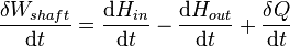
During steady-state operation of a device (see turbine, pump, and engine), any system property within the control volume is independent of time. Therefore, the internal energy of the system enclosed by the control volume remains constant, which implies that dUcv in the expression above may be set equal to zero. This yields a useful expression for the power generation or requirement for these devices in the absence of chemical reactions:
\frac{\delta W_{shaft}}{\mathrm{d}t}=\frac{\mathrm{d}H_{in}}{\mathrm{d}t}- \frac{\mathrm{d}H_{out}}{\mathrm{d}t}+\frac{\delta Q}{\mathrm{d}t} \,

Thermodynamic system


A thermodynamic system is a precisely defined macroscopic region of the universe, often called aphysical system, that is studied using the principles of thermodynamics.
All space in the universe outside the thermodynamic system is known as the surroundings, theenvironment, or a reservoir. A system is separated from its surroundings by a boundary which may be notional or real, but which by convention delimits a finite volume. Exchanges of work, heat, or matter between the system and the surroundings may take place across this boundary. Thermodynamic systems are often classified by specifying the nature of the exchanges that are allowed to occur across its boundary.
A thermodynamic system is characterized and defined by a set of thermodynamic parameters associated with the system. The parameters are experimentally measurable macroscopic properties, such as volume, pressure, temperature, electric field, and others.
The set of thermodynamic parameters necessary to uniquely define a system is called the thermodynamic state of a system. The state of a system is expressed as a functional relationship, the equation of state, between its parameters. A system is in thermodynamic equilibrium when the state of the system does not change with time.

Workdone in a Steady Flow Process

The steady flow equation for unit mass flow, in the differential form, is

                           &q - &w = dh + d(ke) + d(pe)

According to first law of thermodynamics for a closed system, we know that
&q = du +pdv
or
dh = &q +v dp
substituting this value of dh in equation
&q - &w = (&q + v dp) + d(ke) + d(pe)
- &w = v dp + d(ke) + d(pe)

Transmission Fluids


Most of you may believe that lubrication is important to almost every mechanical part. Thus, the transmission fluid also deserves people's attention because it can provide much-needed lubrication to the complex set of gears and other moving parts in the transmission of a vehicle. Both manual and automatic transmissions need the transmission fluid to keep the proper performance.
There are two types of transmission fluid which can be widely used in the vehicles. Those are traditional transmission fluid and synthetic fluid. Although the latter type costs more than the former one, no one can give an exact answer whether the former type is better or not because they both have their own characteristics and can be applied to meet different requirements. For example, synthetic fluid should be used if you drive a high-performance vehicle under demanding conditions on a frequent basis. But in order to keep your car in a good condition, you must serve the vehicle and replace the fluid regularly whatever type of you use.
Now let us talk something about them specifically. The synthetic fluid has become increasingly popular because it doesn't lose its viscosity or coating ability. Moreover, it is also able to transfer heat more evenly for longer periods of time.
Generally, it is man-made, produced from refined oils treated with a variety of chemical additives. As is mentioned before, it can retain their viscosity longer than conventional fluids; as a result, you do not have to change them frequently.
Traditionally, transmission fluid has been petroleum-based. In manual transmissions, the biggest problem is fluid contamination either due to oxidation or friction between the moving parts that shear minute metal particles into the fluid.

Diesel Engines


Attempting to start Diesel engines in cold or sub zero temperatures is extremely difficult and usually an impossible task, unless appropriate accessories has been added to the engine to assist in such starting.
The hard starting problems of diesel engines in below zero / freezing temperatures are caused by two factors. One is the initial cold air being drawn into the turbocharger and compressed into the engine's cylinder head. The second is the fuel itself, is also cold and this sub zero / freezing temperature fuel is sprayed into the cold engine's combustion chamber, where it mixes with the cold air drawn thru turbocharger.
Additional problems will result from fact that a cold starting diesel engine needs to reach at least two hundred (200) rpm to develop a four hundred (400) psi compression pressure to sufficiently compress the air to fuel mixture, and thus, resulting in combustion.
These two problems will result in the diesel fuel being sprayed into the combustion chamber, and it will condense on the cold surfaces of the cylinder liners or cylinder block. This liquid fuel will seep through the piston rings, and fall into the engine's crankcase, diluting the lubricating oil in the process.
Two simple devices can be used to reduce the possibility that these conditions occur. One is by the use of battery heaters and glow plugs. No one device can be used. Usually a combination of several devices will provide an overall efficient starting process.
The efficiency of a battery drops as its temperature drops. A battery that is fully charged at 26 degrees C (80 degrees F) will have its starting capacity drop to approximately forty six percent (46%) available power at 17.7 degrees C below 0 (0 degrees F). Additionally, at this temperature, the engine will be approximately two and a half (2.5) times harder to start at -17.7 C (0 F) degrees due to thicker oil and resistance to movement of internal moving parts. This gets worst at lower temperatures are experienced.
To solve this, one of two common devices is used to heat the battery. One is a padded silicone covered, acid resistant rubber hot pad heater. This operates off of 110/120V and comes in various wattages. The power range can be 60W to 500W, and this can be used to heat the batteries, engine oil pan, fuel tank, hydraulic tank, and the water tank.

Thermal Flow Meter


When performing on-site analysis in the processing plant or similar environment, there are various different ways and approaches that must be employed in order to arrive at the desired result. This should not come as much of a surprise since different plants serve a number of different purposes. As such, it is best to look towards the most comprehensive approach to the operation of the processing system as possible. That means a variety of equipment will need to be installed in order to ensure that the pipeline or vessel transporting liquids will operate in a full service manner. Of the many varied items a processing engineer requires, thermal flow meters serve some of the most helpful functions.

For those curious as to what purpose these devices actually perform, here is a brief overview: they are intended for the purpose of measuring the flow of a fluid by way of examining the thermal properties of the fluid. This is done by examining a controlled and measured amount of heat to the fluid. (Hence, this is where the term thermal derives from) A sensor will then log the results which can be reviewed by the Engineer or operative. The results of this review can then be weighed for a variety of different purposes and results.

While some may assume that the development of thermal flow meters is the result of new advancements in engineering and associated industries, the origin of this type of equipment actually dates back to the very early part of the 20th century. Of course, there have been many modern advancements made in the development of this particular device. This has allowed it to achieve a level of accuracy and function that adds a level of confidence to the process that would not have been possible without such technological achievements.

The engineering and processing industries are fields that are always growing and innovating. The equipment used in these areas often follow suit quite rapidly. That is why there is such great success in the development of systems such as thermal flow meters. They are able to take an age-old concept or system and effectively update it in such a way that it delivers a great help to all manner of relevant environments. To say this delivers a great value to this environment would be tremendous understatement and most Processing and engineering personnel are grateful that such advanced systems exist to aid them in their work.

There are two different methods that thermal flow meters employ to deliver on their intended results. The first process is known as a constant temperature differential approach and the other is a constant current system. The former system employs measurements of heat and gas while the latter method measures heat and the heat of a particular flow stream. Is one better than the other? Honestly, the issue is not whether one is better than the other as much as certain systems are more appropriate for some labs than others. In general, both serve their prime purpose well.

Thermal Mass Flow Technology


Thermal Mass Flow (TMF) technology uses thermodynamic principles to drive actual mass flow. A thermal mass flow sensor can be combined with an integral valve and PID flow controller in one compact, efficient instrument that can accurately control the flow of gases and liquids over a wide range of flow rates.

A pressure sensor can be mounted in place of a flow sensor for applications requiring pressure control. Thermal mass flow products exhibit high repeatability and accuracy, providing an effective way to ensure a reliable and stable process.

HERMAL ENGINEERING IN POWER SYSTEMS

Heat Transfer series looks at the research and development in thermal engineering for power systems that are of significant importance to many scientists who work in power-related industries and laboratories. To be competitive in today's market, the editors say, power systems need to reduce operating costs, increase capacity, and deal with many other tough issues. Among the topics the book covers are: relevance of heat transfer and heat exchangers for development of sustainable energy systems; advanced technologies for clean and efficient energy conversion in power systems; virtual engineering and the design of power systems; and innovative gas turbine cooling techniques.

Aluminum Fabrications


Aluminium fabrication is a challenging task indeed. The special properties of aluminium often pose some serious challenges even to the most experienced welders. For example, aluminum is a very well conductor of heat. At the same time, it has a low melting point. Naturally, it becomes difficult to weld the aluminium sheet without burning at least some portions of it. Also, there are some impurities involved in the aluminium which is important to be got rid of. At the same time, one should preheat the aluminium sheet to ensure that the welding is done properly without any chance of cracks.

Regarding all these actions, the push technique is often considered preferable for the experienced professionals. This is basically the technique pushing the gun away from the welding puddle instead of pulling it towards it. The process ensures better cleaning actions, improved shielding gas coverage and reduced weld contamination. Anyways, it is important that the entire welding is done quickly. Since the thermal conductivity of aluminum is high, you need to use higher voltage and amperage settings. Also, you have to have high weld travel speed to ensure that the work is done during the right temperature.

When it comes to shielding gas for aluminum welding, the argon is the most popular option. This is largely because of its ability to clean and penetrate. However, if someone is welding 5XXX series of aluminum alloys, the use of a mixture of argon and helium is preferred. This will reduce the formation of magnesium oxide in the welding process.

Another tricky task for aluminum welding is to select the welding filler wire. Ideally, you should pick up a wire that has a very similar melting point to the base material. This is crucial, the narrower the gap between the filler and the base material, the easier the process will be. Also, you should prefer a wire with a large diameter.

One of the greatest challenges with the aluminum welding is the crater cracking. In fact, this is the most common factors that cause failure in aluminum welding. The crack occurs largely because of the higher rate of thermal expansion of aluminum. However, the risk is even greater when you are welding the concave craters as their surface tears at the time of contraction. Therefore, the welder must ensure that a convex or mound shape is developed during the welding. This will compensate the amount of contraction at the time of cooling down. Finally, you should always choose the power source tool according to the method of transfer spray arc.

Types Of Pressure Vessels


When a container is pressurized then pressure is exerted against the walls of the vessels. Pressure is always normal to the surface regardless of the shape. Pressure vessel is a container that has pressure different from the atmospheric pressure. There are many types of pressure vessel they are; thin walled, thick walled, strong tanks, transportable containers, propane bottles and gas cylinders. Pressure vessel is a container that holds liquid, vapor or gas at different pressure other then atmospheric pressure at the same elevation. Generally, a pressure vessel is considered to be thin-walled if its radius is larger than 5 times its wall thickness. Under this condition, the stress in the wall may be considered uniform. Thin wall pressure vessels are in fairly common use. There are two specific types of pressure vessels they are; cylindrical pressure vessels and spherical pressure vessels. Under this condition, the stress in the wall may be considered uniform. The stress in thin walled vessel varies from a maximum value at the inside surface to a minimum value at the outside surface of the vessel. Storage tanks are a category of thin walled pressure vessel.

A thick walled pressure vessel is the one that its wall is 10 % thicker than inside diameter. Thick walled pressure elements working in high temperatures in power stations, chemical and petro chemical industries are subjected to damage as a result of high temperature, mechanical loading and corrosive environment. These factors cause thermal fatigue, creep-fatigue and other processes leading to degradation. When subject to internal and external pressure stress and strain exist in thick walled pressure vessel. They have high tensile strength and can withstand maximum stress.

Transportable containers are the most common pressure vessel and potentially the most ignored type. These are mass produced and require testing every 10 years for propane and gas. Steel pressure vessels are designed to perform the dual purposes air storage and partial separation of moisture. These are provided with all standards so as to operate safely. Pressure vessels have to be designed to perform efficiently at high pressure. Pressure vessel must be free of any cracks or leakages, thereby ensuring complete safety to the surrounding environment. Cracked and damaged vessel may result in leaks or rupture failure. Rupture failure may cause considerable damage to life and property. The safe design, installation, operation and maintenance of pressure vessel in accordance with appropriate codes and standards are necessary for workers safety and health.